Experimental Beechcraft Model 35 Bonanza NX80040, circa 1946. (Roger Bilstein Collection, San Diego Air & Space Museum Archives)
22 December 1945: Test pilot Vern Louis Carstens made the first flight of Beech Aircraft Corporation’s new Beechcraft Model 35 Bonanza. Five prototypes were built. The first two were used as static test articles. The third prototype, NX80150, serial number 3, was the first to fly.
“. . . Wichita residents and Beech employees “lined the runway” to watch the first flight of the Beechcraft Bonanza. “The town turned out and the plant all but shut down for the occasion,” said Vern L. Carstens, retired Beech Aircraft chief test pilot who made the historic flight. From the day of its first flight, the Beechcraft V-tailed Bonanza has set industry standards for high performance single engine aircraft. The Bonanza received its type certificate on March 25, 1947. . . .”
—The Salina Journal, Salina, Kansas, Sunday, 27 December 1970, at Page 25, Columns 1–7.
The first Bonanza to fly was the number three prototype, NX80150. (San Diego Air & Space Museum Archives)
On 26 October 1946, one of the Model 35 prototypes, possibly s/n 3, was destroyed:
During a dive test to determine the maximum dive velocity, a landing gear door buckled under the air loads, causing the door to be forced open. Air was then forced into the landing gear recess on the underside of the wing, and internal pressure built up to the point where the wing failed.
—Department of Transportation, Transportation Systems Center Beech V-Tail Bonanza Task Force Report, 1985.
Harry Lawrence Reiter Jr.
Harry Lawrence Reiter, Jr., Chief Flight Research Pilot for Beechcraft, was killed when the airplane broke up and crashed 15 miles east of Wichita. An observer, Robert King, was able to escape.
The registration for NX80150 was cancelled 18 May 1948.
The Beechcraft Model 35 Bonanza is a single-engine, four-place all-metal light civil airplane with retractable landing gear. The Bonanza has the distinctive V-tail with a 30° dihedral which combined the functions of a conventional vertical fin and rudder, and horizontal tail plane and elevators.
The Model 35 was 25 feet, 2 inches (7.671 meters) long with a wingspan of 32 feet, 10 inches (10.008 meters) and height of 6 feet, 6½ inches (1.994 meters). It had an empty weight of 1,458 pounds (661 kilograms) and gross weight of 2,550 pounds (1,157 kilograms.)
An early production Beechcraft Model 35 Bonanza, NC2703V, c/n D-79. (Beech Aircraft Corporation via Larry Westin)
The first flyable prototype, NX80150, was equipped with an air-cooled, normally aspirated 289.31-cubic-inch-displacement (4.741 liter) Lycoming O-290-A horizontally-opposed 4-cylinder engine, rated at 125 horsepower at 2,600 r.p.m., and 130 horsepower at 2,800 r.p.m (five minute limit).
Prototype number four, s/n 4, NX80040, and the following production models used a more powerful air-cooled, 471.24-cubic-inch-displacement (7.72 liter) Continental Motors, Inc., E185 horizontally-opposed 6-cylinder engine. This engine was rated at 165 horsepower at 2,050 r.p.m. The Bonanza used a two-bladed electrically-controlled variable-pitch R-100 propeller with a diameter of 7 feet, 4 inches (2.235 meters), made of laminated wood.
The “V-tail Bonanza” had a maximum speed of 184 miles per hour (296 kilometers per hour) at Sea Level, and a cruise speed of 175 miles per hour (282 kilometers per hour) at 10,000 feet (3,048 meters). Its service ceiling was 18,000 feet (5,486 meters). With full fuel, 40 gallons (151.4 liters), the airplane had a range of 750 miles (1,207 kilometers).
The Beechcraft 35 was in production from 1947 to 1982. More than 17,000 Model 35s and the similar Model 36 were built.
Beechcraft Model 35 Bonanza NX80040. (Hans Groenhoff Photographic Collection, Smithsonian Institution National Air and Space Museum NASM-HGC-201)
Grumman F-14A-1-GR Tomcat Bu. No. 157980, just before its first flight, Calverton, Long Island, New York, 21 December 1970. (Northrop Grumman Corporation)
21 December 1970: At the Grumman Aerospace Corporation plant, Calverton, Long Island, New York, Chief Test Pilot Robert Kenneth Smyth and Project Test Pilot William Howard Miller took off on the very first flight of the F-14A-1-GR Tomcat, Bu. No. 157980.
The F-14 is a long-range fleet defense interceptor designed to operate from the United States Navy’s aircraft carriers. It is a two-place, twin-engine Mach 2+ fighter. The most notable feature are its variable geometry wings (“swing wings”), similar to those of the General Dynamics F-111.
A Grumman F-14A Tomcat during test flight. (U.S. Navy)
The Grumman F-14A Tomcat (Grumman has a long history of naming its fighter aircraft after various cats, e.g., Wildcat, Hellcat, Tigercat, Panther, Cougar, Tiger) is 62 feet, 8 inches (19.101 meters) long with its wingspan varying from 33 feet, 3 inches (10.135 meters) when swept fully aft (overswept), and 64 feet, 1 inches (19.510 meters) when fully extended. The airplane has an overall height of 16 feet, 0 inches (4.879 meters). It has an empty weight of 38,188 pounds (17,322 kilograms) and maximum takeoff weight of 72,566 pounds (32,915 kilograms).
The fighter was initially powered by two Pratt & Whitney JTF10A (TF30-P-412A) afterburning turbofan engines. The JTF10A is a two-spool axial-flow engine. It has a 3-stage fan section, 13-stage compressor section (6 low- and 7 high-pressure stages) and 4-stage turbine (1 high- and 3 low-pressure stages). The engine has a Maximum Continuous Power rating of 10,800 pounds of thrust (48.041 kilonewtons) at 14,300 r.p.m. (N2); Intermediate Power, 12,350 pounds (54.936 kilonewtons) at 14,800 r.p.m. (45-minute limit); and a Maximum Power of 20,900 pounds (92.968 kilonewtons) at 14,780 r.p.m., with afterburner (45-minute limit). The engine is 18 feet, 7.59 inches (5.679 meters) long, 4 feet, 2.5 inches (1.283 meters) in diameter, and weighs 3,971 pounds (1,801 kilograms).
The first Grumman F-14A Tomcat, 21 December 1970. (U.S. Naval Institute)
Cruise speed for the F-14A is 497 knots (572 miles per hour/920 kilometers per hour). It has a maximum speed of 805 knots (926 miles per hour (1,491 kilometers per hour) at Sea Level (Mach 1.22) and 1,314 knots (1,512 miles per hour/2,434 kilometers per hour) at 38,000 feet (11,582 meters) (Mach 2.29). The airplane’s service ceiling is 41,000 feet (12,497 meters), and its combat ceiling is 57,600 feet (17,556 meters) at 1,030 knots (1,185 miles per hour/1,907 kilometers per hour), Mach 1.80. The Tomcat has a combat radius of 741 nautical miles (853 statute miles/1,372 kilometers), and its maximum ferry range is 1,840 nautical miles (2,117 miles/3,407 kilometers).
The Tomcat is armed with one 20 mm General Electric M61A1 Vulcan six-barrel Gatling gun with 676 rounds of ammunition. It can carry a combination of Hughes AIM-54A Phoenix long range air-to-air missiles, as well as AIM 7E Sparrow and AIM 9H Sidewinders. The F-14 has the capability of simultaneously engaging six independent targets with the Phoenix missile. The AIM-54A is a radar-guided Mach 5 missile with a range of 115 statute miles (185 kilometers). It has a 135 pound (61.2 kilograms) proximity-fused blast fragmentation warhead.
The Grumman F-14 was in production from 1970 until 1991, in three variants, the F-14A, F-14B and F-14D. A total of 712 Tomcats were built. The fighter remained in service with the United States Navy until 2006. 79 F-14As were provided to the Imperial Iranian Air Force, prior to the Islamic revolt. An unknown number of these remain in service with the Islamic Republic of Iran Air Force.
Grumman Chief Test Pilot Robert Kenneth Smyth. (Northrop Grumman Corporation)
21 December 1916: Harry George Hawker, M.B.E., A.F.C., made the first flight of the Sopwith Camel at Brooklands Aerodrome, Surrey, England. This airplane would become the Royal Air Force’s most successful fighter of World War I.
The Sopwith Camel F.1 was a British single-place, single-engine biplane fighter, produced by the Sopwith Aviation Co., Ltd., Canbury Park Road, Kingston-on-Thames. The airplane was constructed of a wooden framework, with the forward fuselage being covered with aluminum panels and plywood, while the aft fuselage, wings and tail surfaces were covered with fabric.
The length of the Camel F.1 varied from 18 feet, 6 inches (5.639 meters) to 19 feet, 0 inches (5.791 meters), depending on which engine was installed. Both upper and lower wings had a span of 28 feet, 0 inches (8.534 meters) and chord of 4 feet, 6 inches (1.372 meters). They were separated vertically by 5 feet (1.524 meters) at the fuselage. The upper wing had 0° dihedral, while the lower wing had 5° dihedral and was staggered 1 foot, 6 inches (0.457 meters) behind the upper wing. The single-bay wings were braced with airfoil-shaped streamline wires. The overall height of the Camel also varied with the engine, from 8 feet, 6 inches (2.591 meters) to 8 feet, 9 inches (2.667 meters).
The heaviest Camel F.1 variant used the Le Rhône 180 h.p. engine. It had an empty weight of 1,048 pounds (475 kilograms). Its gross weight of 1,567 pounds (711 kilograms). The lightest was equipped with the Gnôme Monosoupape 100 horsepower engine, with weights of 882 pounds (400 kilograms) and 1,387 pounds (629 kilograms), respectively.
Front view of a Sopwith Camel F.I (Unattributed)
The first Camel was powered by an air-cooled 15.268 liter (931.72 cubic inches) Société Clerget-Blin et Cie Clerget Type 9 nine-cylinder rotary engine which produced 110 horsepower at 1,200 r.p.m. and drove a wooden two-bladed propeller. Eight different rotary engines ¹ from four manufacturers, ranging from 100 to 180 horsepower, were used in the type.
The best performance came with the Bentley B.R.1 engine (5.7:1 compression ratio). This variant had a maximum speed of 121 miles per hour (195 kilometers per hour) at 10,000 feet (3,048 meters), and 114.5 miles per hour (184 kilometers per hour) at 15,000 feet (4,572 meters). It could climb to 6,500 feet (1,981 meters) in 4 minutes, 35 seconds; to 10,000 feet (3,048 meters) in 8 minutes, 10 seconds; and 15,000 feet (4,572 meters) in 15 minutes, 55 seconds. It had a service ceiling of 22,000 feet (6,706 meters). Two other Camel variants could reach 24,000 feet (7,315 meters).
The Bentley B.R.1 rotary engine was designed by Lieutenant Walter Owen Bentley, Royal Naval Air Service (later, Captain, Royal Air Force), based on the Clerget Type 9, but with major improvements. It used aluminum cylinders shrunk on to steel liners, with aluminum pistons. The Bentley B.R.1 (originally named the Admiralty Rotary, A.R.1, as it was intended for use by the Royal Navy) was an air-cooled, normally-aspirated 17.304 liter (1,055.948 cubic inches) right-hand tractor, nine-cylinder rotary engine with a compression ratio of 5.7:1. It was rated at 150 horsepower at 1,250 r.p.m. The B.R.1 was 1.110 meters (3 feet, 7.7 inches) long, 1.070 meters (3 feet, 6.125 inches) in diameter and weighed 184 kilograms (406 pounds.) The engine was manufactured by Humber, Ltd., Coventry, England, and Vickers, Ltd., Crayford.
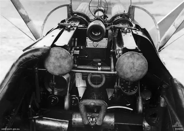
The instruments and armament of a Sopwith Camel from No. 4 Squadron, AFC. (Australian War Memorial)
The Camel was armed with two fixed, forward-firing .303-caliber (7.7×56mmR) Vickers machine guns, synchronized to fire forward through the propeller. These guns were modified for air cooling. Some night fighter variants substituted Lewis machine guns mounted above the upper wing for the Vickers guns. Four 25 pound (11.3 kilogram) bombs could be carried on racks under the fuselage.
The Sopwith Camel was a difficult airplane to fly. Most of its weight was concentrated far forward, making it unstable, but, at the same time making the fighter highly maneuverable. The rotary engine, with so much of its mass in rotation, caused a torque effect that rolled the airplane to the right to a much greater degree than in airplanes equipped with radial or V-type engines. A skilled pilot could use this to his advantage, but many Camels ended upside down while taking off.
Major William G. Barker, RAF, with an upside-down Sopwith Camel F.1 of No. 28 Squadron, Italy, 1918. (Library and Archives Canada)
Twelve manufacturers ² produced 5,490 Sopwith Camels between 1916 and 1920. By the end of World War I, it was becoming outclassed by newer aircraft, however it was the single most successful fighter of the war, shooting down 1,294 enemy aircraft.
One single fighter, Major William Barker’s Sopwith Aviation Co., Ltd., Camel F.1 B.6313 shot down 46 enemy aircraft, more than any other fighter in history.
It is believed that only seven Sopwith Camels still exist.
Wing Commander William George Barker, V.C., D.S.O. with Bar, M.C. with 2 Bars, Croix de Guerre, with his Sopwith Camel F.1. (Library and Archives Canada)
Milton O. Thompson with a Lockheed JF-104A Starfighter at Edwards Air Force Base, circa 1962. The JF-104A is similar to the one he ejected from, 20 December 1962. (NASA)
20 December 1962: Milton Orville Thompson, a NASA test pilot assigned to the X-15 hypersonic research program, was conducting a weather check along the X-15’s planned flight path from Mud Lake, Nevada, to Edwards Air Force Base in California, scheduled for later in the day. Thompson was flying a Lockheed F-104A-10-LO Starfighter, Air Force serial number 56-749, call sign NASA 749.
NASA 749, a Lockheed JF-104A Starfighter, 56-749, with an ALSOR sounding rocket on a centerline mount, at Edwards Air Force Base. (NASA)
In his autobiography, At the Edge of Space, Thompson described the day:
“The morning of my weather flight was a classic desert winter morning. It was cold, freezing in fact, but the sky was crystal clear and there was not a hint of a breeze—a beautiful morning for a flight.”
Completing the weather reconnaissance mission, and with fuel remaining in the Starfighter’s tanks, Milt Thompson began practicing simulated X-15 approaches to the dry lake bed.
X-15 pilots used the F-104 to practice landing approaches. The two aircraft were almost the same size, and with speed brakes extended and the flaps lowered, an F-104 had almost the same lift-over-drag ratio as the X-15 in subsonic flight. Thompson’s first approach went fine and he climbed back to altitude for another practice landing.
Lockheed F-104A-10-LO Starfighter 56-749 (NASA 749) carrying an ALSOR sounding rocket on a centerline mount. (NASA)
When Milt Thompson extended the F-104’s flaps for the second simulated X-15 approach, he was at the “high key”— over Rogers Dry Lake at 35,000 feet (10,668 meters) — and supersonic. As he extended the speed brakes and lowered the flaps, NASA 749 began to roll to the left. With full aileron and rudder input, he was unable to stop the roll. Adding throttle to increase the airplane’s airspeed, he was just able to stop the roll with full opposite aileron.
Thompson found that he could maintain control as long as he stayed above 350 knots (402 miles per hour/648 kilometers per hour) but that was far too high a speed to land the airplane. He experimented with different control positions and throttle settings. He recycled the brake and flaps switches to see if he could get a response, but there was no change. He could see that the leading edge flaps were up and locked, but was unable to determine the position of the trailing edge flaps. He came to the conclusion that the trailing edge flaps were lowered to different angles.
Thompson called Joe Walker, NASA’s chief test pilot, on the radio and explained the situation:
I told him the symptoms of my problem and he decided that I had a split trailing edge flap situation with one down and one up.
He suggested I recycle the flap lever to the up position to attempt to get both flaps up and locked. I had already tried that, but I gave it another try. Joe asked if I had cycled the flap lever from the up to the takeoff position and then back again. I said no. I had only cycled the flap lever from the up position to a position just below it and then back to the up position. Joe suggested we try it his way. I moved the flap lever from the up position all the way to the takeoff position and then back to the up position. As soon as I moved the lever to the takeoff position, I knew I had done the wrong thing.
The airplane started rolling again, but this time I could not stop it. The roll rate quickly built up to the point that I was almost doing snap rolls. Simultaneously, the nose of the airplane started down. I was soon doing vertical rolls as the airspeed began rapidly increasing. I knew I had to get out quick because I did not want to eject supersonic and I was already passing through 0.9 Mach. I let go of the stick and reached for the ejection handle. I bent my head forward to see the handle and then I pulled it. Things were a blur from that point on.
—At the Edge of Space: The X-15 Flight Program, by Milton O. Thompson, Smithsonian Institution Press, Washington and London, 1992. Chapter 5 at Pages 119–120.
Impact crater caused by the crash and explosion of Milt Thompson’s Lockheed JF-104A Starfighter, 20 December 1962. (NASA)
As Thompson descended by parachute he watched the F-104 hit the ground and explode in the bombing range on the east side of Rogers Dry Lake. He wrote, “It was only 7:30 a.m. and still a beautiful morning.”
Boeing 707-121 N708PA, photographed during its second flight on the afternoon of 20 December 1957. (Boeing)Boeing 707-121 N708PA makes its first takeoff at 12:30 p.m. on a rainy afternoon, 20 December 1957. (Boeing)
20 December 1957: The first production Boeing 707 jet-powered commercial airliner, N708PA, made its first flight at Renton, Washington. Alvin M. “Tex” Johnston, Boeing’s Chief of Flight Test, was in command, with co-pilot James R. Gannet and flight engineer Tom Layne. Takeoff was at 12:30 p.m., PST. Poor weather limited the first flight to just 7 minutes. The new airliner landed at Boeing Field. Later that day, a second flight was made, this time with a duration of 1 hour, 11 minutes.
N708PA (Serial Number 17586, Line Number 1) was a Model 707-121. The new airliner had been sold to Pan American World Airways, the launch customer, as part of an order for twenty 707s in October 1955.
Boeing’s Chief of Flight Test, Alvin M. “Tex” Johnston, in the cockpit of of the 367–80, “Dash Eighty,” 1954. (LIFE Magazine via Jet Pilot Overseas)
The Boeing Model 707 was developed from the earlier Model 367–80, the “Dash Eighty,” prototype for an air-refueling tanker which would become the KC-135A Stratotanker. The 707 was a four-engine jet transport with swept wings and tail surfaces. The leading edge of the wings were swept at a 35° angle.
N708PA was initially used for flight testing by Boeing. Once this was completed, it was prepared for commercial service and delivered to Pan American at San Francisco International Airport (SFO), 30 November 1958. Pan Am named the new airliner Clipper Constitution.
Boeing 707-121 N708PA under maintenance at Renton, Washington. (Boeing)
In February 1965, the airliner was upgraded to 707-121B standards, which replaced the original turbojet engines with quieter, more efficient Pratt & Whitney JT3D-1 turbofan engines which produced 17,000 pounds of thrust. The wing inboard leading edges were modified to the design of the Model 720 and there was a longer horizontal tail plane.
Clipper Constitution flew for Pan Am for nearly seven years, until 17 September 1965 when it crashed into Chances Peak, a 3,002 foot (915 meters) volcano on the Caribbean island of Montserrat. The point impact was 242 feet (74 meters) below the summit. All aboard, a crew of 9 and 21 passengers, were killed.
Boeing 707-121 N708PA, with both Boeing and Pan American corporate markings. (Unattributed)
The Boeing Model 707-121 was a four-engine jet transport with swept wings and tail surfaces. The leading edge of the wings were swept at a 35° angle. The airliner had a flight crew of four: pilot, co-pilot, navigator and flight engineer.
The 707-121 was 145 feet, 1 inch (44.221 meters) long with a wing span of 130 feet, 10 inches (39.878 meters). The top of the vertical fin stood 42 feet, 5 inches (12.929 meters) high. The 707 pre-dated the ”wide-body” airliners, having a fuselage width of 12 feet, 4 inches (3.759 meters). The airliner’s empty weight is 122,533 pounds (55,580 kilograms). Maximum take off weight is 257,000 pounds (116,573 kilograms).
The first versions were powered by four Pratt & Whitney Turbo Wasp JT3C-6 turbojet engines, producing 11,200 pounds of thrust (49,820 kilonewtons), and 13,500 pounds (60.051 kilonewtons) with water injection. This engine was a civil variant of the military J57 series. It was a two-spool axial-flow turbojet engine with a 16-stage compressor and 2 stage turbine. The JT3C-6 was 11 feet, 6.6 inches (3.520 meters) long, 3 feet, 2.9 inches (0.988 meters) in diameter, and weighed 4,235 pounds (1,921 kilograms).
At MTOW, the 707 required 11,000 feet (3,352.8 meters) of runway to take off.
The 707-121 had a maximum speed of 540 knots (1,000 kilometers per hour). It’s range was 2,800 nautical miles (5,186 kilometers).
The Boeing 707 was in production from 1958 to 1979. 1,010 were built. Production of 707 airframes continued at Renton until the final one was completed in April 1991. As of 2011, 43 707s were still in service.
Boeing 707-121 N708PA retracting its landing gear after takeoff at Seattle Tacoma Airport. (Unattributed)


 The first flyable prototype, NX80150, was equipped with an air-cooled, normally aspirated 289.31-cubic-inch-displacement (4.741 liter) Lycoming O-290-A horizontally-opposed 4-cylinder engine, rated at 125 horsepower at 2,600 r.p.m., and 130 horsepower at 2,800 r.p.m (five minute limit).