Miss Harriet Quimby, 1911, (Leslie Jones Collection, Boston Public Library)
1 August 1911: After 33 flight lessons over a four-month period at the Moisant Aviation School at Hempstead, Long Island, New York, Harriet Quimby took her flight test and became the first woman to receive a pilot’s license, Number 37, from the Aero Club of America. She was “America’s First Lady of the Air.”
She was well-known throughout the United States and Europe, and wore a purple satin flying suit.
On 16 April 1912 she became only the second pilot to fly across the English Channel when she flew from Dover to Calais in 59 minutes with a Blériot monoplane.
Eleven months after receiving her pilot’s license, 1 July 1912, Harriet Quimby was killed when she fell from her Blériot XI during a flying demonstration at Squantum, Massachusetts.
Harriet Quimby and her Blériot XI. (Library of Congress)
1 August 1907: The progenitor of the United States Air Force was established.
August 1, 1907
OFFICE MEMORANDUM NO. 6
Brigadier General James Allen, Chief Signal Officer 1906–1913. (U.S. Army)
An Aeronautical Division of this office is hereby established, to take effect this date. This division will have charge of all matters pertaining to military ballooning, air machines, and all kindred subjects. All data on hand will be carefully classified and plans perfected for future tests and experiments. The operations of this division are strictly confidential, and no information will be given out by any party except through the Chief Signal Officer of the Army or his authorized representative.
Captain Charles DeF. Chandler, Signal Corps, is detailed in charge of this division, and Corporal Edward Ward and First-class Private Joseph E. Barrett will report to Captain Chandler for duty in this division under his immediate direction.
J. Allen, Brigadier General, Chief Signal Officer of the Army
The United States Army had used stationary balloons for battlefield reconnaissance since the Civil War. The Army’s first self-propelled aircraft, though, was Signal Corps Dirigible No. 1, a rigid airship buoyed by hydrogen, and which could carry two crewmen at just under 20 miles per hour (32 kilometers per hour), with a flight duration of 2 hours.
Signal Corps Dirigible No. 1 at Fort Myer, Virginia, 1908 (U.S. Army)
Dirigible No. 1 had been designed and built by Thomas Scott Baldwin of Hammondsport, New York. On 3 August 1908, the airship, Baldwin No. 8, was presented to the Army for trials. Although the the Baldwin No. 8 reached an average speed of just 19.61 miles per hour (31.56 kilometers per hour). It demonstrated the required endurance of two hours, averaging 14 miles per hour (22.5 kilometers per hour). Although the airship’s speed was short of the requirement, on 5 August, the Army purchased it from Baldwin for $5,737.59.
The U.S. Army’s first aviators, Lieutenants Benjamin D. Fulois, Thomas Etholen Selfridge and Frank P. Lahm were taught to fly the airship. Lahm and Fulois made the first flight of an all-Army crew on 26 August.
Signal Corps Dirigible No. 1 was assigned to the Signal Corps Post at Fort Omaha, Nebraska, where the Army had a balloon factory. It was operated there until 1912. The airships envelope needed to be replaced, and unwilling to spend money for that, the airship was sold.
Responding to an Army specification for a heavier than air craft, Orville Wright brought a Wright Model A Flyer to Fort Myer to demonstrate it. On 17 September 1908, The Model A, with Wright as pilot and Lieutenant Selfridge as a passenger, crashed. Wright was seriously injured, but Selfridge died. He was the first person to be killed in an airplane crash.
The following year, an improved airplane, the Wright Military Flyer was shipped to Fort Myer, arriving 18 June 1909. Tests were conducted over the next several weeks. The Military Flyer achieved a two-way average 42.583 miles per hour (68.531 kilometers per hour), over a 5 mile (8.05 kilometers) course, and demonstrated its endurance at 1 hour, 12 minutes, 40 seconds. On 2 August 1909, the United States Army purchased its first airplane, at a cost of $25,000. Because the Military Flyer exceeded the Army’s requirements in both speed and endurance, bonuses were paid totaling $5,000. The Wright biplane was designated Signal Corps Airplane No. 1.
The Wright 1909 Military Flyer being fueled at Fort Myer. Orville Wright is to the right side of the photograph. (U.S. Air Force)
The airplane was used to train Signal Corps pilots at Fort San Antonio, Texas, and was crashed and rebuilt several times. After just two years’ service, it was retired. The Army gave the airplane to the Smithsonian Institution. It is on display at the National Air and Space Museum.
Apollo 15: Jim Irwin loads the LRV for EVA-1, 31 July 1971. The mountain behind the Lunar Module is Hadley Delta. (David Scott/NASA)
At 13:52:31 UTC, 31 July 1971, (T + 120:18:31) the Lunar Roving Vehicle was deployed from Apollo 15’s Lunar Module, Falcon. This was the first time that an LRV had been used on the surface of the moon.
The LRV was a four-wheeled, electrically-powered, surface transportation vehicle designed to carry two astronauts and their equipment to explore areas farther away from the landing site than they would be able to by walking.
The LRV was built by Boeing at Kent, Washington. prime contractor. The wheels, electric motors and suspension system were built by a General Motors subsidiary in Santa Barbara, California.
Three-view drawing of Lunar Roving Vehicle with dimensions (Lunar Roving Vehicle Operations Handbook LS006-002-2H, Page 1 – 3, Fig. 1 – 1, The Boeing Company LRV Systems Engineering, Huntsville, AL)
The lunar rover was constructed of welded aluminum tubing and hinged to allow folding to store aboard the lunar module. It had two folding seats for the astonauts. The four tires were ingeniously constructed of woven steel strands (0.083 cm). about 122 inches (3.10 meters) long. The wheelbase was 90 inches (2.29 meters) and the track was 72 inches (1.83 meters). It was 44.8 inches (1.14 meters) high.
Jim Irwin with LRV at Hadley Rille, 31 July 1971. (Dave Scott/NASA)Jim Irwin with LRV at Hadley Rille, 30 July 1972. Detail from image above. (Dave Scott/NASA)
The mass of the empty LRV was 210 kilograms (463 pounds on Earth, but only about 77 pounds on the surface of the Moon), and it was capable of transporting a payload of 490 kilograms (about 81 “moon-pounds”).
The four tires were ingeniously constructed of woven steel strands (0.083 centimeters diameter). The tire was 81.8 centimeters (32.2 inches) in diameter, and 23 centimeters (9.1 inches) wide. The aluminum wheels were 80 centimeters (31.5 inches) in diameter and 24 centimeters (9.4 inches) wide. The tires’ traction was enhanced by “chevrons” made of titanium.
Lunar Roving Vehicle wheel and tire assembly. (NASM-A197508300000_PS02)
Each wheel was driven by a DC electric motor, capable of 0.25 horsepower at 10,000 r.p.m. There was a 80:1 speed reduction.
Electric power for the vehicle was provided by two 36-volt (+5/-3 volts) silver-zinc potassium hydroxide batteries with a total capacity of 121 amperes/hour. The batteries were not rechargeable.
The Apollo 15 landing crew made three excursions with the LRV, traveling a total distance of 27.8 kilometers (17.3 statute miles) in 3 hours, 26 minutes driving time. The maximum speed reached was 12 km/h (7.5 mph). NASA reported that “the longest single traverse was 12.5 km [7.8 miles] and the maximum range from the LM was 5.0 km. [3.1 miles]“
Apollo 15’s three LRV traverses. Image from the Lunar Reconnaissance Orbiter. (NASA/GSFC/Arizona State University)
Commandant Antoine de Saint-Exupéry, Forces Aériennes Françaises Libres. (John Phillips)
31 July 1944, famed French aviator and author Antoine de Saint-Exupéry (Antoine Marie Jean-Baptiste Roger comte de Saint Exupéry), flying for the Forces Aériennes Françaises Libres (the Free French Air Force), departed Borgo Airfield on the island of Corsica. He was on a reconnaissance mission of the Rhône Valley. His aircraft was a Lockheed F-5B-1-LO Lightning, serial number 42-68223, an unarmed photo reconnaissance variant of the P-38J Lighting twin-engine fighter.
Saint-Exupéry was never seen again.
Antoine de Saint-Exupéry flying his Lockheed F-5B-1-LO Lightning near Alghero on the coast of Sardinia, 1944. (John e Annamaria Phillips Foundation)
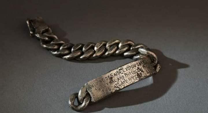
In 1998 a fisherman found his silver identity bracelet on the sea floor south of Marseilles. Parts of the aircraft were recovered in 2003.
Antoine de Saint-Exupéry’s identity bracelet. (WikiTree)
“Saint-Ex” wrote Night Flight;Flight to Arras;Wind, Sand and Stars’ and The Little Prince, as well as many other works. He was a gifted writer.
A pilot boards his Lockheed P-38 Lightning at sunset. (U.S. Air Force)
This photograph shows SSGT Maynard H. Smith with a Browning .50-caliber machine gun at the left waist position of a B-17 Flying Fortress. (U.S. Air Force)
31 July 1923: The original patent application, Serial No. 654,955, for the legendary Browning .50-caliber machine gun was filed with the United States Patent Office on 31 July 1923. Patent Number 1,628,226 was issued to the estate of John Moses Browning by the Patent Office on 10 May 1927.
The majority of United States combat aircraft during World War II were armed with the Browning Machine Gun, Caliber .50, AN-M2. The machine gun could be mounted as a fixed weapon in the aircraft’s wings or nose, in flexible mounts, or power-operated turrets.
Three Browning .50-caliber machine guns and belted ammunition installed in the left wing of a Vought-Sikorsky F4U-1 Corsair, 11 August 1942. (Vought-Sikorsky)
The basic aircraft Browning machine gun, cal. .50, AN-M2. . . is an automatic, recoil-operated, belt-fed, air-cooled machine gun. The metallic link disintegrating belt is used in all firing of the gun. The gun is designed for all cal. .50 aircraft machine gun installations. By properly repositioning some of the component parts, ammunition may be fed into the gun from either the right or the left side.
—TM9-225 War Department Technical Manual, BROWNING MACHINE GUN, CALIBER .50, AN-M2, AIRCRAFT, BASIC, 28 January 1947, Section II., Paragraph 3. General, at Page 2
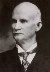
Illustration of the basic .50-caliber Browning machine gun, AN-M2. (War Department)John Moses Browning
The Browning Machine Gun (“BMG”) was designed by John Moses Browning, who had also designed the Automatic Pistol, Caliber .45, M1911, the standard sidearm of the U.S. military for 74 years; the Rifle, Caliber .30, Automatic, Browning, M1918 (best known as the “Browning Automatic Rifle” or “BAR”); the Browning Machine Gun, Caliber .30, M1919; and the Browning Hi-Power, a 9 × 19 mm double-action semiautomatic pistol designed for Fabrique National (FN) of Herstal, Belgium.
The AN-M2 aircraft machine gun has an overall length of 56.25 inches (1.429 meters) and weighs 61.00 pounds (27.67 kilograms). The barrel is cylindrical, and 36.00 inches (0.91 meters) long. It is surrounded by a barrel jacket with ventilation holes to dissipate heat. The bore has 8 rifled-grooves with a right-hand twist, making one complete turn in every 15.00 inches (0.381 meters).
John Browning with a water-cooled version of his .50-caliber machine gun. (Museums at Union Station/The Wall Street Journal)
The basic AN-M2 gun could be modified to be manually fired with the substitution of a “spade grip” back plate. It could also be changed from left-hand ammunition feed to right hand by reversing some internal parts.
The M2 machine gun had a rate of fire of 750 to 850 rounds per minute.
Armorers load disintegrating-link belts of .50-caliber ammunition for the eight machine guns of a Republic P-47 Thunderbolt. (U.S. Air Force)
Ammunition is ball, armor-piercing, armor-piercing-incendiary, tracer, blank (no bullet), and dummy. The armor-piercing cartridge, M2, has a muzzle velocity of 2,840 feet per second (866 meters per second) and maximum range of 7,275 yards (6,652 meters). Some .50-caliber rounds have muzzle velocities as high as 3,450 feet per second (1,052 meters per second), though most range from 2,730 fps to 2,900 fps (832–884 m/s). The ammunition produces chamber pressures of approximately 55,000 pounds per square inch (3,792 bar).
A gunner fires the two Browning .50-caliber machine guns of a B-17’s ball turret. (U.S. Air Force)
The .50 BMG cartridge is 5.45 inches (13.843 centimeters) long (NATO 12.7 × 99). The rimless, tapered bottleneck case is 3.91 inches (9.931 centimeters) long, with diameters of 0.560 inches (14.224 millimeters) at the neck, 0.735 inches (18.669 millimeters) at the shoulder, and 0.804 inches (20.422 millimeters) at the base. The bullet is 2.31 inches (58.67 millimeters) long, with a maximum diameter of 0.510 inches (12.954 millimeters) and weighs 706.7 grains (1.6 ounces, 45.8 grams).
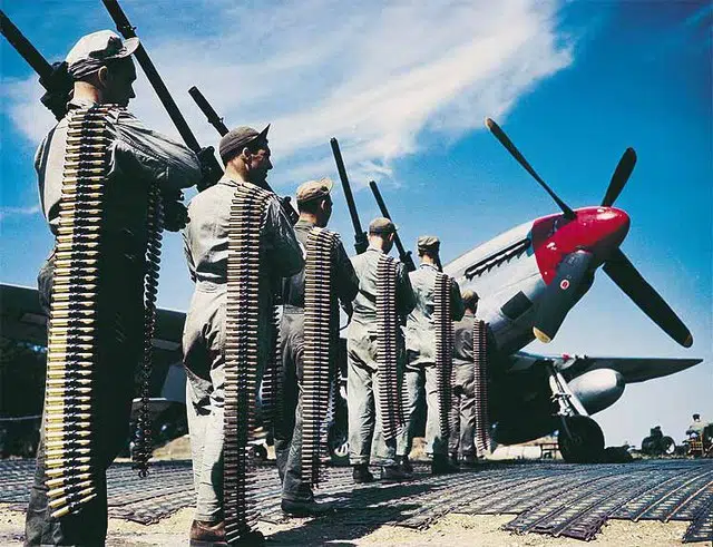
Lieutenant Clark Gable with a belt of linked .50-caliber machine gun cartridges. The colored tips of the bullets identify armor piercing, incendiary or tracer ammunition.Armorers carry Browning AN-M2 .50-caliber machine guns and belts of linked ammunition to a P-51 Mustang. (U.S. Air Force)